Scope of Project
This project aids in the parametric design and construction of a tower based completely on a single modular unit. It demonstrates the possibilities of emergent complexity based on a thoughtful combination of simple parts and simple rules.
This was originally developed as a collaboration with Woodlab Designs as an art project for Burning Man.
A gallery of resulting images and animations can be found on the Hoberman Tower portfolio page.
Hoberman Circle
A Hoberman Circle is an isokinetic structure that is capable of folding down to a fraction of its normal size by the scissor-like action of its joints. It’s possible to make this structure with a very small number of repeating, modular parts.
Hoberman Tower
Stacking multiple fabricated Hoberman Circles will create a tower structure. We can slightly change the contraction and rotation of each layer progressively. The culmination of these adjustments can result in unlimited variations in the final structure.
Programming Overview
This project was designed in Grasshopper. Grasshopper is a parametric modeling and visual programming plugin for Rhino, a 3D CAD modeling software package.
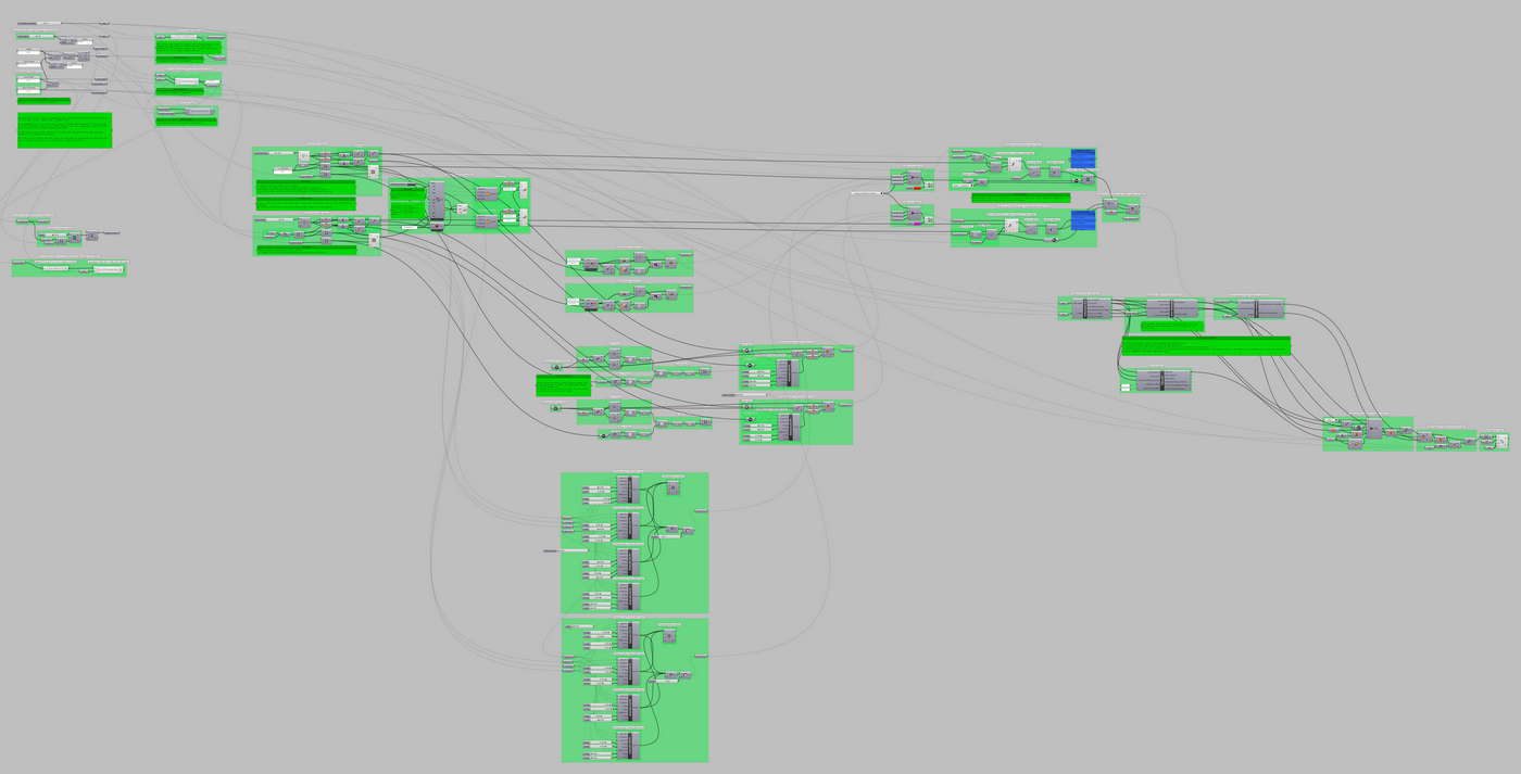
The image below shows the overall definition which flows from upper-left to bottom-right:
- Input parameters are set.
- Fundamental equations are solved.
- A user interface (UI) is developed for fluid design changes.
- The designs in the UI are then interpreted into a set of construction parameters.
- The fundamental components are constructed.
- They are rendered in various levels of complexity and realism.
- Then the rendered components are copied, positioned, and arrayed which completes the tower.
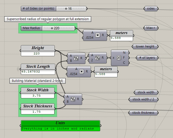
Initializing Parameters
For a basic Hoberman Circle we need the following parameters:
- Width will be chosen by a Radius. A Hoberman Circle contracts so we’ll define the size from one of the extremes — the maximum possible radius.
- The number of sides (or star points) are also needed to calculate the geometry.
That’s all we need for a theoretical model. We’re designing for a real structure so we’ll also need:
- Height will set the vertical limit and help us determine how many layers are needed for the tower.
- Material dimensions. I’m assuming that a US Standard two-by-four will be used. Along with the height, material dimensions will determine how many layers will be constructed.
Since we are likely to use available stock material, we’ll want feedback on the required stock length based on our chosen parameters. This helps us choose a balance of parameters that can be made with available materials. If the feedback tells us a stock length that’s greater than what’s available, we can increase the number of sides or reduce the radius to arrive at feasible dimensions.
- Stock Length is calculated later in the definition, but I’ll place an info box here for the easy feedback.
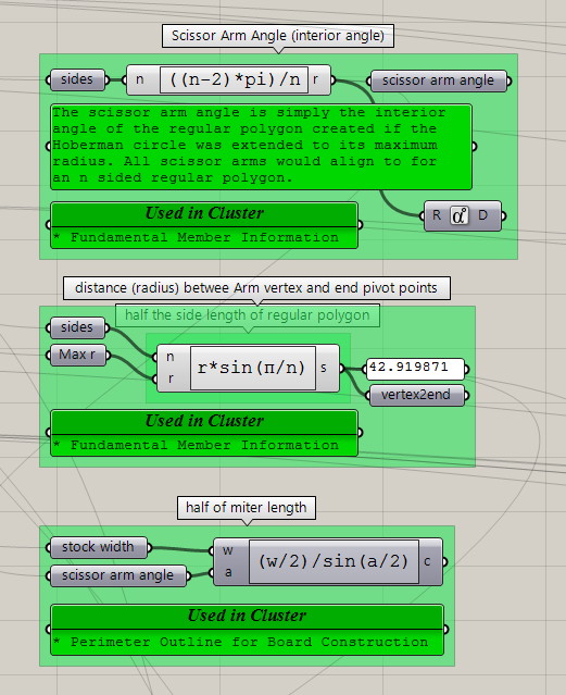
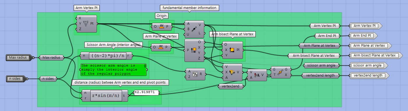
Initial Calculations
The fundamental geometry of a Hoberman Circle is based on a regular polygon of n sides. We’ll need to know:
- The interior angle of the regular polygon
- The distance between the scissor arm vertex and end pivot points
Since we intend to build from wood stock, we’ll need:
- Miter cut details where two arms will butt join to make a single scissor arm
Control Frames as an Intuitive UI
I find joy in building simple UI elements that are intuitive and encourage creative exploration. For each layer, Radius and Rotation, combined with Height will allow us to create unlimited attractive variations for our fundamental geometry. Combined we can create twisting features and elevation profiles.
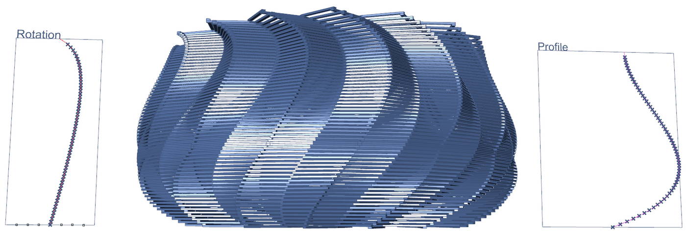
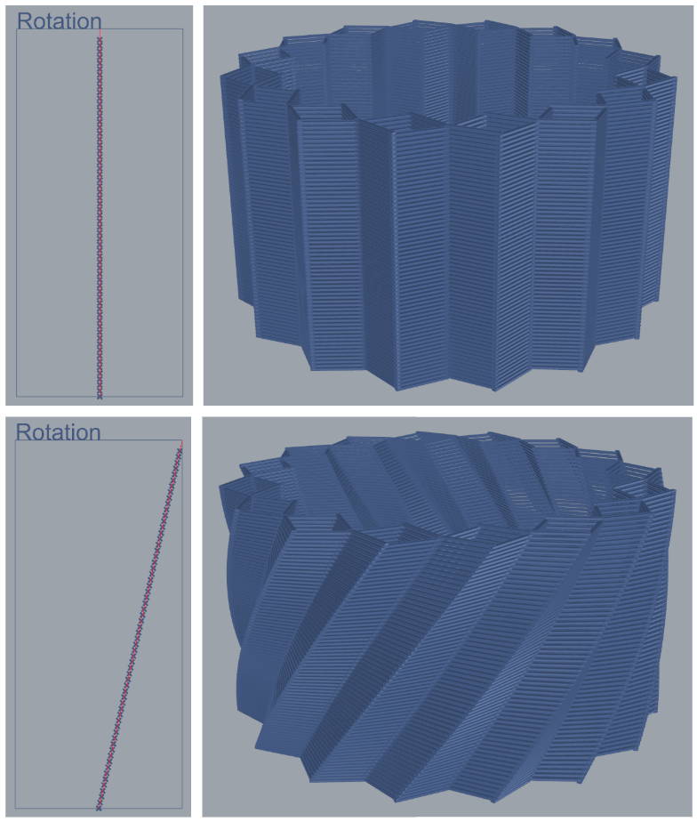
Rotation Frame
Frame width is associated with rotation. Frame height is associated with tower height.
Any curve within the frame serves as a function where every point of the curve is a direct relationship between layer height and the rotation for that layer.
In the first example frame, all layers have the same rotation. It will produce a structure without any spin. The second example shows a straight line at an angle. This will result in a consistent helical twist.
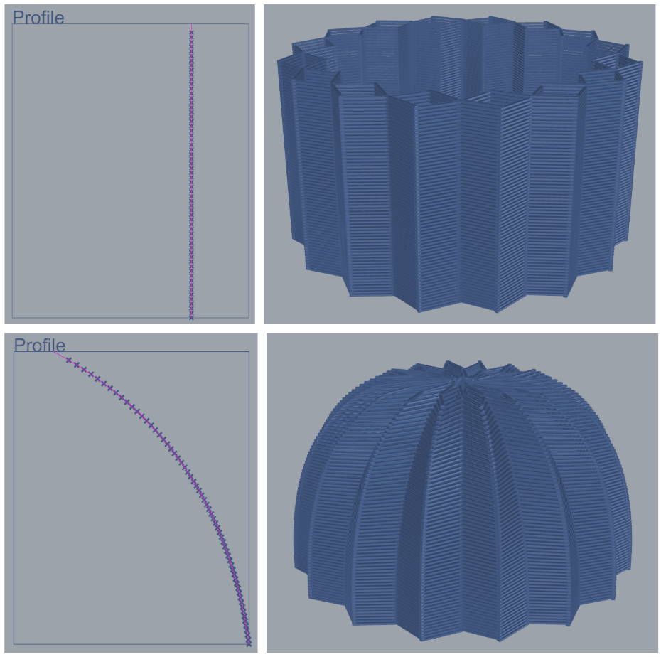
Profile
Frame width is associated with radius, from minimum to maximum. Frame height is associated with tower height.
Any curve within the frame serves as a function where every point of the curve is a direct relationship between layer height and the radius for that layer. Stacking each layer will result in a tower whose elevation profile matches the curve in this frame.
In the first example frame, the curve is straight up at about 75% of max radius. It will produce a straight, vertical structure. The second example shows a curve whose base starts at 75% width and progressively closes down to a small radius. This will result in a dome shaped building profile.
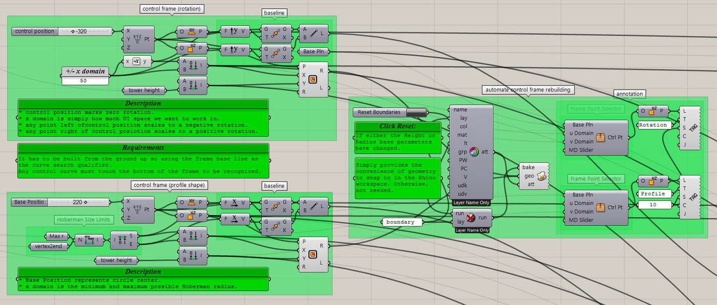
Control Frame
I choose a position for each frame and an appropriate domain for the x and y axis. Then automatically generate a frame object in Rhino space so that we can snap to it when playing with the design curves. There are a couple frame labels for clarity and there’s a redraw button for if the fundamental parameters are adjusted.
Control Curve Identification
To further improve the ease of design, I reduce workflow friction by automatically recognizing a curve that is contained in the Control Frame. This way we can build a collection of curves and simply swap them out to revisit and compare our favorites.

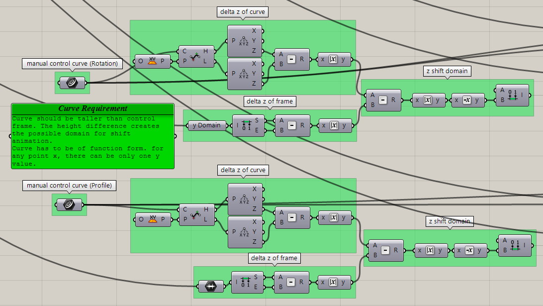
Curve Animation
Sometimes an animation communicates a feature more effectively. And usually an animation just looks cool. In addition to the curve identification above, any curve can be selected and moved through the frame to create a tower then animates as the changes propagate. Here the domains for range of movement are calculated based on the differences between curve size and frame size.
Single Point Animation Controls
Another useful animation alternative is to independently animate each control point of a curve. This level of fine control opens up more flexibility for the outcome of our animations. To simplify controlling all points with a single animation slider, each point can be assigned their own path parameters from start to finish. I wrap up the complexity of this into a Grasshopper Cluster, simplifying our environment to show only the control parameters.
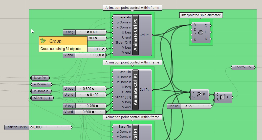
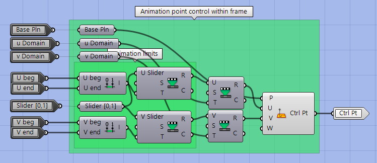
Cluster – Animation Control Point
Inside this cluster, we see that; A movement domain is created on a chosen plane; we choose the beginning and end positions for the point position; a common animation slider will be remapped from 0 to 1 to the respective positions in a linear progression.
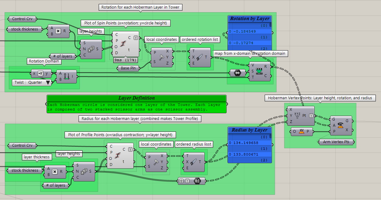
Layer Vertex Points
Here’s where the design UI is transcribed into useful arrays of data. Points along the Rotation and Profile shape curves are determined by dividing the vertical frame domain at the respective Hoberman layer heights. The intersection of each of these layers with the design curve provide our data points. The (u,v) coordinates of these points are (rotation, height) and (radius, height) for the respective design curves. For each layer this data is combined into a set of real vertex points to build a Hoberman Circle from. Each point provides the height, radius contraction, and rotation.
Scissor Assembly
The scissor assembly is comprised of two identical scissor arms. The core arm geometry is determined in the first cluster, described below. The arm dimensions to be fashioned from lumber are determined in the second cluster. The reference planes for the positioning of both arm and assembly are produced in the third cluster. These planes vary by Hoberman radius and layer height. They provide the transformation data to build the entire tower from the individual parts.
Each scissor arm is made from two identical arms, butt joined together at the interior angle of the Hoberman Circles equivalent regular polygon. The scissor arm alone looks like an obtuse isosceles triangle without the base.
Two scissor arms are stacked on top of each other and their respective center vertices are joined on an axis with pivot hardware. The ends of the arms will connect similarly by pivot hardware to the arms of an adjacent scissor assembly.
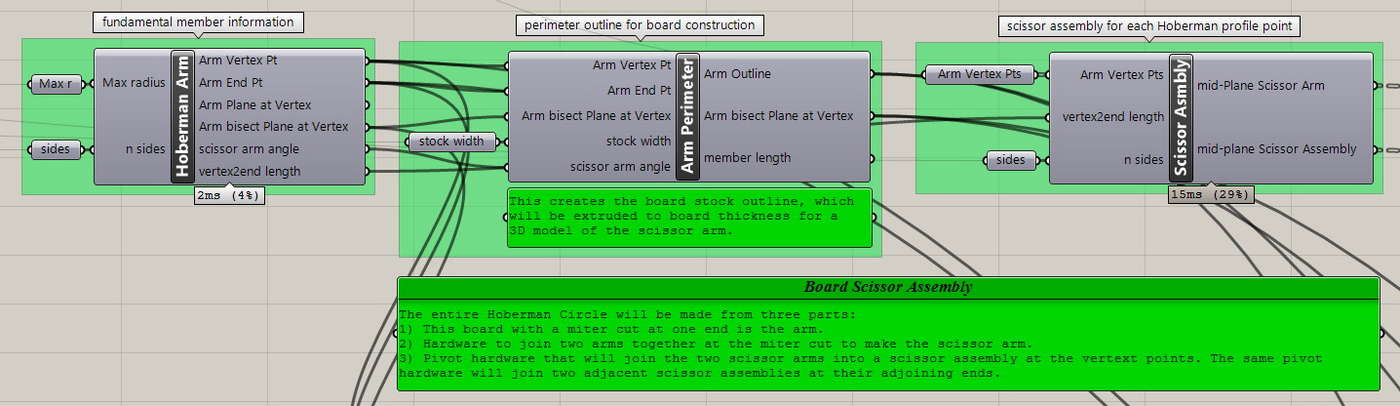
Cluster – Arm Geometry
This is the most fundamental unit of the Hoberman Circle. At full extension, the Hoberman Circle takes the form of a regular polygon and some insight about the structure is easily garnered.
- The scissor arm angle is equal to the interior angle of the respective regular polygon.
- Each side of the scissor arm is half the length of a side of the respective regular polygon.
Here, based on the maximum radius and number of sides chosen, we establish the vertex and endpoint that make a line that represents the arm as the fundamental unit of the assembly. While we are working with the fundamental geometry we also provide:
- The scissor arm plane, which will be used to reflect a single arm across the scissor arm bisecting angle when building the full scissor assembly.
- The rest of the geometry could come in useful and is easy to provide while we are working with it.
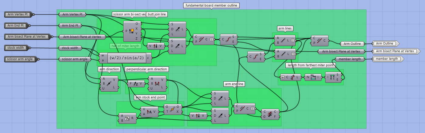
Cluster – Board Outline
Planning for production, we model the arm as it would be built from standard, available materials. The cross-sectional dimension of any board can be entered. The outline produced represents the plan view of the board and includes a miter cut at the proper angle where two arms will be butt joined together. Later we can extrude this outline to make a 3D dimensional model of the parts.
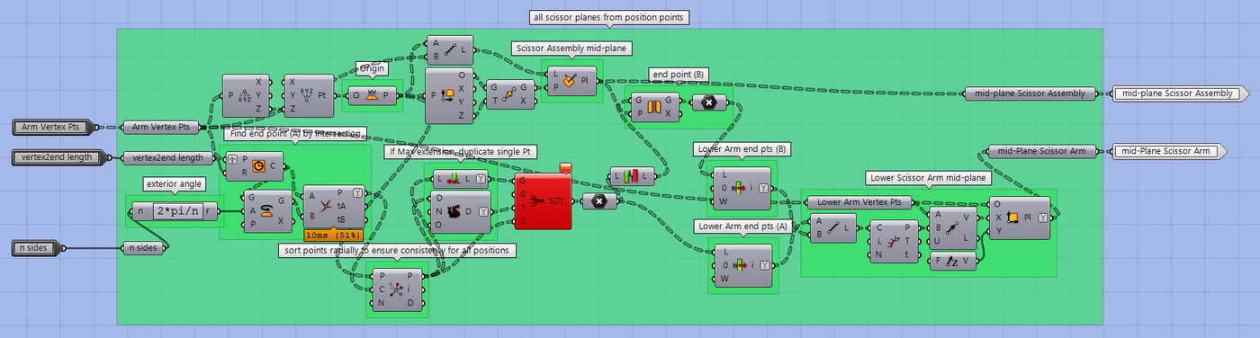
Cluster -Scissor Planes
Using the provided vertex point that shows the degree of contraction, we determine an assembly mid-plane and a scissor arm mid-plane. The assembly mid-plane is used to ‘reflect’ a single scissor arm to become the assembly. The scissor arm mid-plane provides both a mirror plane to reflect the single arm sub-component and the scissor assembly lever angle associated with the circle’s contraction. Note that these two are coplanar only when a Hoberman Circle is fully extended to its respective regular polygon shape.
Rendering Complexity and Compiling the Tower
Rendering all the parts takes GPU and CPU time. I like to build in the freedom to switch levels of complexity easily based on my changing workflow. For instant feedback while troubleshooting the code or when exploring final design variations, I switch to line or outline for instant feedback. When a design variation looks interesting, I’ll switch to a full rendering of all the parts for review or presentation.
- Line: Fundamental Hoberman Geometry
- Outline: Flat outline of board construction
- Surface: Flat (2D) surface of board construction
- 2×4: 3D model of board construction
- Pipe: 3D pipe construction alternative
Once the geometry complexity is chosen, for each layer I build a single section of the Hoberman Circle from the basic parts — the Scissor Assembly. And then repeat those in a polar array for the complete circle and subsequent tower. Note: it’s more computationally efficient to transform a single built or rendered part as many times as needed than to transform all the base geometry and build or render each piece after.

Results
With this Grasshopper definition, we can devise countless designs based on one set of modular assemblies. Each assembly is also modularized, from only 3 parts: A single board with a miter cut at one one end and two drilled holes; Butt joining hardware; And, pivot hardware.